UML
- 13가지 Modeling Language를 합침 (Unified Modeling Language)
- 사용
- 데이터 모델링 (Entity Relation Diagram)
- 비즈니스 모델링 (workflow)
- object 모델링
- 컴포넌트 모델링
UML Semantics
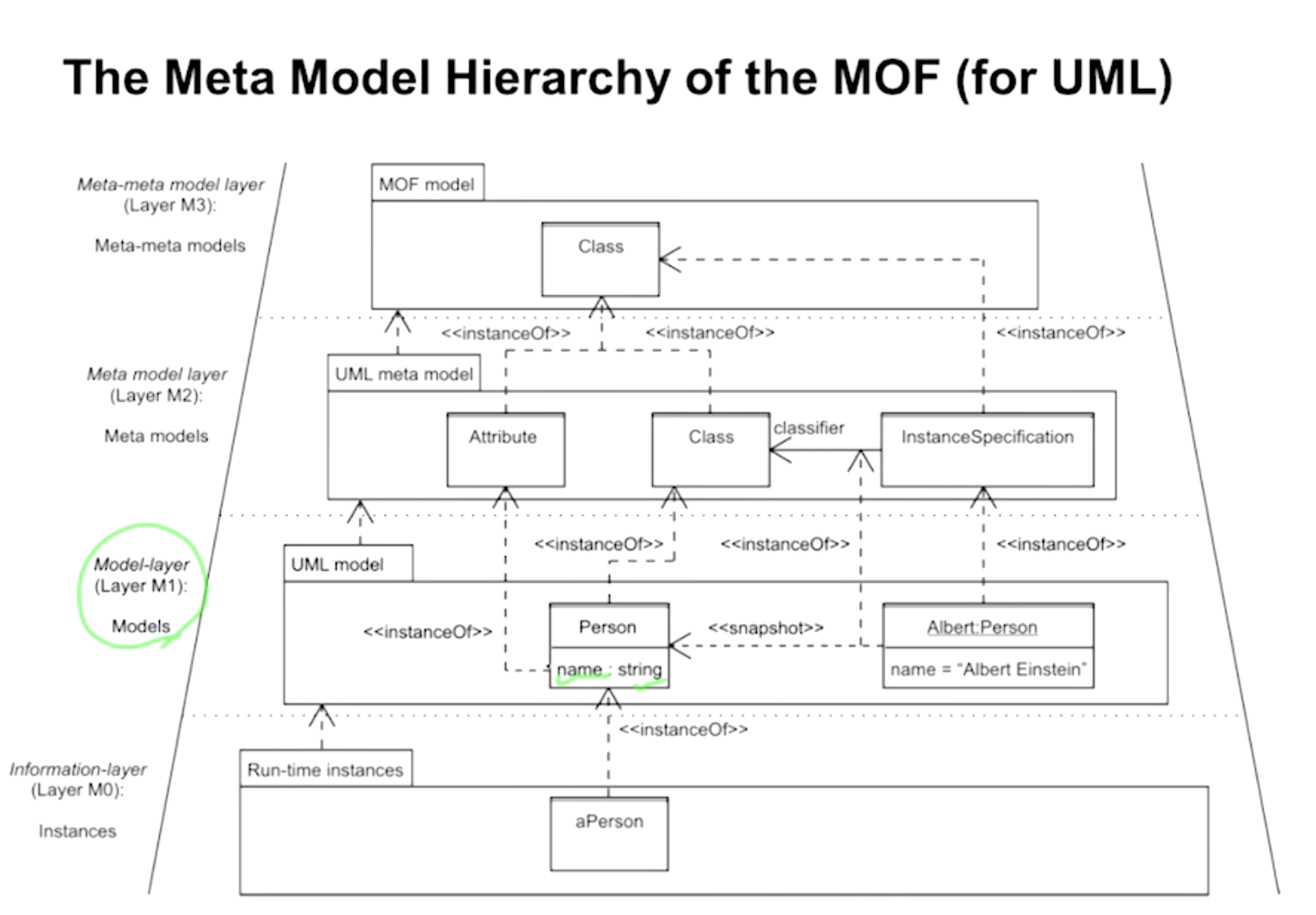
- 4-layer metamodel architecture : instance → model → meta model → meta-meta model
- MOF(Meta Object Facility) 계층
- Layer M3 : Meta-meta model layer (The MOF model) : 다이어그램 샘플 (ex. .NET의 Profile)
- Layer M2 : Meta model layer (The UML meta model) : 다이어그램을 정의
- Layer M1 : Model layer (The UML model) : class, 시퀀스 다이어그램 등 실제로 그리는 작업
- Layer M0 : Information layer (the Application) : 실제로 런타임에 어떤 식으로 동작하는지
UML 2.0 Diagrams
- 총 13가지 UML 다이어그램
※ Diagram, Structure Diagram, Behaviour Diagram(기울임) : abstract class (new 불가능)- OOA : Usecase Diagram (+ Domain model)
- OOD : Sequence Diagram, Class Diagram

- Use Case Diagram
- external actor가 시나리오기반으로 텍스트를 사용해서 그리는 다이어그램
- 방법 : 양쪽에 actor를 적고 중간에 use case를 적어 관계를 잇고 + Description으로 시나리오 적음
- Class Diagram
- class가 어떤 attribute, operation을 가지고 있고 서로 어떻게 연결되어있는지 보여주는 다이어그램
- 두 가지 용도
- OOA에서 Domain model용으로 그림
- OOD에서 Design class diagram(DCD) 용으로 그림

- Object Diagram
- 위의 class diagram에서 1:*의 *(instances)가 특정 시간에 몇 개인지 구체적으로 정리한 다이어그램
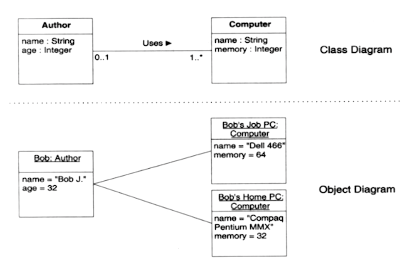
- 위의 class diagram에서 1:*의 *(instances)가 특정 시간에 몇 개인지 구체적으로 정리한 다이어그램
- Package Diagram
- class를 패키지로 묶은 모습을 그린 다이어그램
- Logical architecture (physical X)
- Example
- 모자 그려져 있는 네모 : Package
- 네모 안에 대문자로 시작 : Class
- 네모 안에 소문자로 시작(or 밑줄) : Object

- Component Diagram
- 컴포넌트(개발의 단위)와 그의 관계를 그린 다이어그램
- 실제 Deploy된 것이 아닌 logical한 다이어그램
- Example
- 우측에 수첩 모양있는 네모 : 컴포넌트
- 왼쪽에 동그라미 연결되어있는 컴포넌트 : 데이터를 전달하는 컴포넌트(provider)

- Composite Structure Diagram
- 컴포넌트 다이어그램을 계층적으로, 내부적인 모습을 그린 것
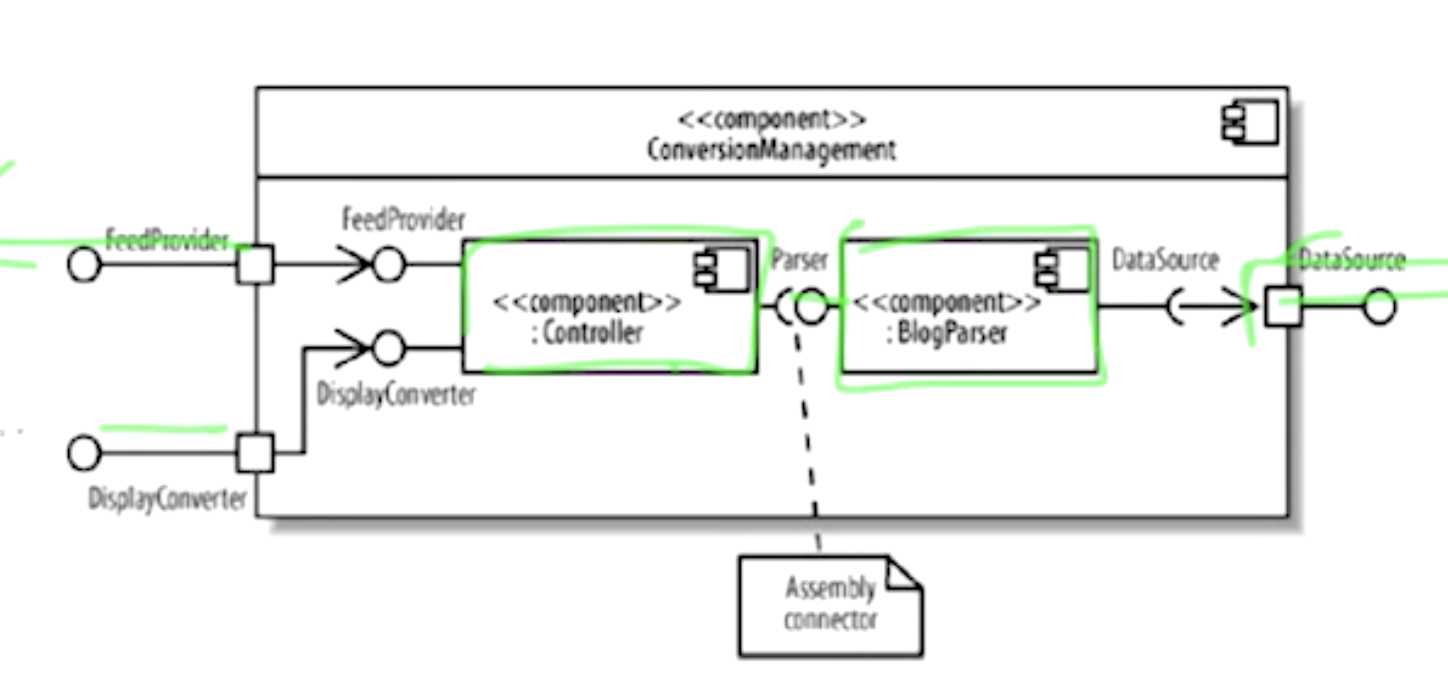
- 컴포넌트 다이어그램을 계층적으로, 내부적인 모습을 그린 것
- Deployment Diagram
- PC(OS), Server 등 런타임 configuration의 모습과 그 내부의 컴포넌트를 그린 다이어그램

여기까지가 Structured Diagram - PC(OS), Server 등 런타임 configuration의 모습과 그 내부의 컴포넌트를 그린 다이어그램
- Sequence Diagram
- 시간 sequence에 따라(위에서 밑으로) use case의 특정 시나리오에서 object의 커뮤니케이션을 그린 다이어그램
- 단점 : Object가 많고 시나리오가 크면 Size가 큼
- 적용 상황 : 주로 사용
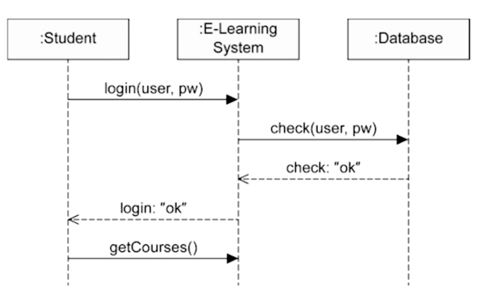
- Communication Diagram (Collaboration diagram)
- Sequence Diagram과 달리 시간 흐름을 나타내지 않아 Size가 작음
- 적용 상황 : 누군가에게 설명하거나 text book에 시나리오 설명할 때

- Timing Diagram
- 주어진 시간 단위 내의 object의 행위를 보여주는 다이어그램
- 시간이 아닌 Timing(순서)를 보여줌 (왼쪽에서 오른쪽으로)
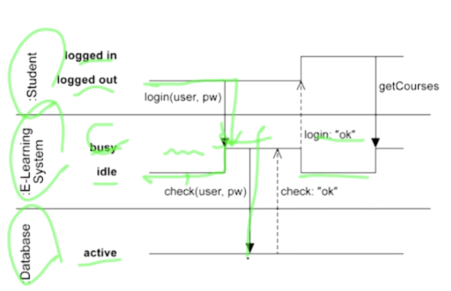
- 주어진 시간 단위 내의 object의 행위를 보여주는 다이어그램
- Interaction Overview Diagram
- 상호작용의 전반적인 것을 그린 다이어그램
- 기본적으로 Activity Diagram(Flow chart)을 그리고 내부 노드에 sequence diagram, communication diagram을 그림
- 적용 경우 : 전체 시나리오 확인하거나 system test 만들 때 사용
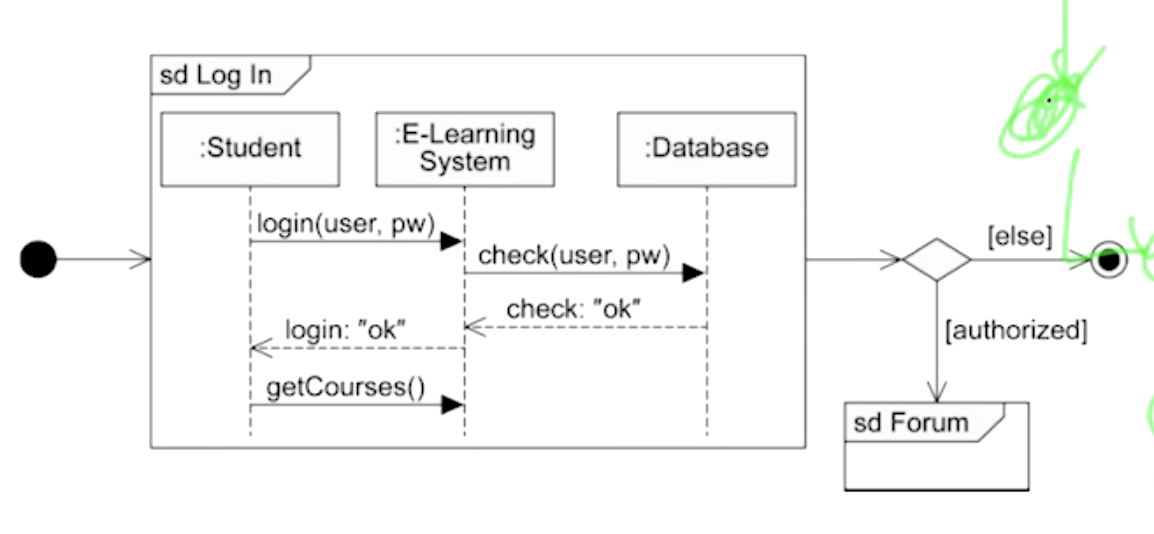
여기서부터 behavior diagram - State Diagram
- state가 변하면서 entity의 상태 변화나 이벤트를 그린 다이어그램
- 보통, 시스템이 state 기반으로 움직이면 사용

- Activity Diagram
- 비즈니스 프로세스를 명세할 때 사용하는 flow chart, DFD
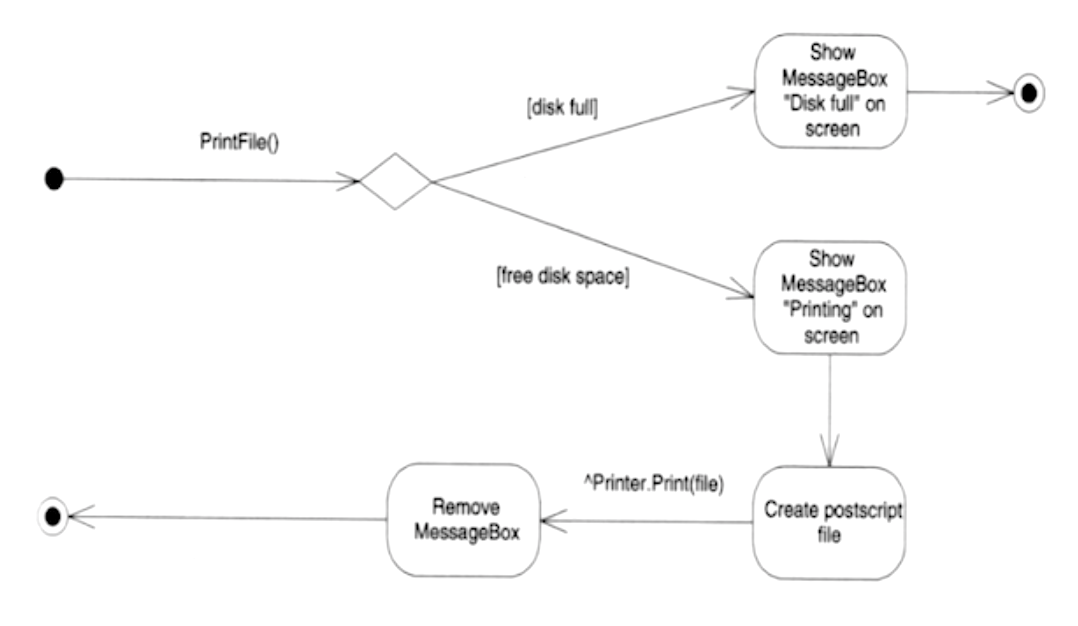
- 비즈니스 프로세스를 명세할 때 사용하는 flow chart, DFD


반응형
'💻 개발IT > UML' 카테고리의 다른 글
| 7. Component Diagram (0) | 2022.02.26 |
|---|---|
| 6. Activity Diagram (0) | 2022.02.26 |
| 5. Statechart Diagram (0) | 2022.02.26 |
| 4. Sequence Diagram (0) | 2022.02.25 |
| 3. Class Diagram (0) | 2022.02.25 |
| 2. Use Case Diagram (0) | 2022.02.25 |


